- 您现在的位置:买卖IC网 > Sheet目录891 > ZL9117MIRZ (Intersil)IC DC/DC MODULE 17A 21QFN
�� �
�
�ZL9117M�
�Functional� Description�
�I� 2� C/SMBus� Communications�
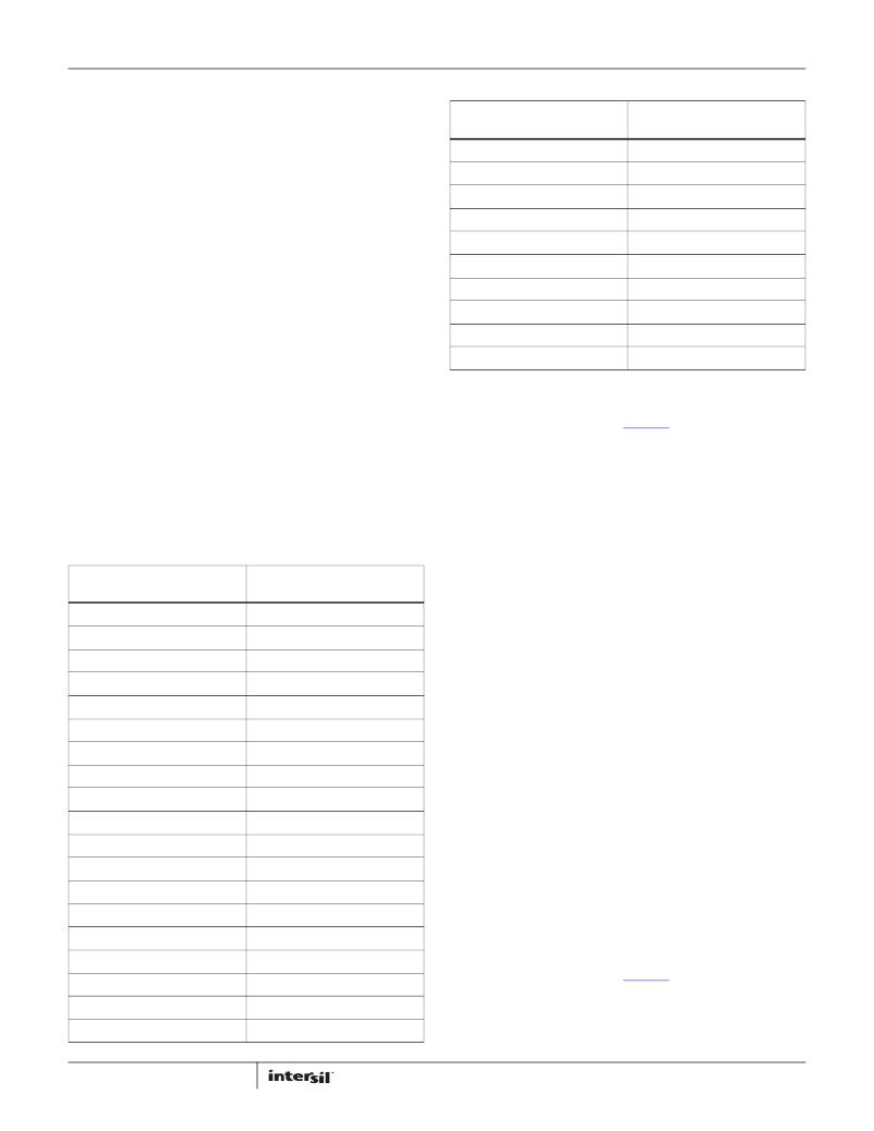
�TABLE� 1.� OUTPUT� VOLTAGE� RESISTOR� SETTINGS� (Continued)�
�V� OUT� R� SET�
�(V)� (k� ?� )�
�The� ZL9117M� provides� an� I� 2� C/SMBus� digital� interface� that�
�enables� the� user� to� configure� all� aspects� of� the� module� operation�
�as� well� as� monitor� the� input� and� output� parameters.� The�
�ZL9117M� can� be� used� with� any� I� 2� C� host� device.� In� addition,� the�
�module� is� compatible� with� SMBus� version� 2.0.� Pull-up� resistors�
�are� required� on� the� I� 2� C/SMBus� as� specified� in� the� SMBus� 2.0�
�specification.� The� ZL9117M� accepts� most� standard� PMBus�
�commands.� When� controlling� the� device� with� PMBus� commands,�
�it� is� recommended� that� the� enable� pin� is� tied� to� SGND.�
�The� SMBus� device� address� and� VOUT_MAX� are� the� only�
�parameters� that� must� be� set� by� external� pins.� All� other� device�
�parameters� can� be� set� via� the� I� 2� C/SMBus.� The� device� address� is�
�set� using� the� SA� pin.� VOUT_MAX� is� determined� as� 10%� greater�
�than� the� voltage� set� by� the� VSET� pin.� Standard� 1%� resistor� values�
�are� used� between� the� respective� pin� and� SGND.�
�1.80�
�1.90�
�2.00�
�2.10�
�2.20�
�2.30�
�2.50�
�2.80�
�3.00�
�3.30�
�61.9�
�68.1�
�75�
�82.5�
�90.9�
�100�
�110�
�121�
�133�
�147�
�Output� Voltage� Selection�
�The� output� voltage� may� be� set� to� a� voltage� between� 0.6V� and�
�3.6V� provided� that� the� input� voltage� is� higher� than� the� desired�
�output� voltage� by� an� amount� sufficient� to� prevent� the� device�
�from� exceeding� its� maximum� duty� cycle� specification.�
�The� VSET� pin� is� used� to� set� the� output� voltage� to� levels� as� shown�
�in� Table� 1.� The� R� SET� resistor� is� placed� between� the� VSET� pin� and�
�SGND.�
�TABLE� 1.� OUTPUT� VOLTAGE� RESISTOR� SETTINGS�
�The� output� voltage� may� also� be� set� to� any� value� between� 0.6V�
�and� 3.6V� using� a� PMBus� command� over� the� I� 2� C/SMBus�
�interface.� See� Application� Note� AN2033� for� details.�
�The� RSET� resistor� program� places� an� upper� limit� in� output�
�voltage� setting� through� PMBUS� programming� to� 10%� above� the�
�value� set� by� the� resistor.�
�Soft-start� Delay� and� Ramp� Times�
�It� may� be� necessary� to� set� a� delay� from� when� an� enable� signal� is�
�received� until� the� output� voltage� starts� to� ramp� to� its� target�
�value.� In� addition,� the� designer� may� wish� to� precisely� set� the� time�
�V� OUT�
�(V)�
�0.60�
�0.65�
�0.70�
�0.75�
�0.80�
�0.85�
�0.90�
�0.95�
�1.00�
�1.05�
�1.10�
�1.15�
�1.20�
�1.25�
�1.30�
�1.40�
�1.50�
�1.60�
�1.70�
�10�
�R� SET�
�(k� ?� )�
�10�
�11�
�12.1�
�13.3�
�14.7�
�16.2�
�17.8�
�19.6�
�21.5�
�23.7�
�26.1�
�28.7�
�31.6�
�34.8�
�38.3�
�42.2�
�46.4�
�51.1�
�56.2�
�required� for� V� OUT� to� ramp� to� its� target� value� after� the� delay�
�period� has� expired.� These� features� may� be� used� as� part� of� an�
�overall� in-rush� current� management� strategy� or� to� precisely�
�control� how� fast� a� load� IC� is� turned� on.� The� ZL9117M� gives� the�
�system� designer� several� options� for� precisely� and� independently�
�controlling� both� the� delay� and� ramp� time� periods.�
�The� soft-start� delay� period� begins� when� the� EN� pin� is� asserted�
�and� ends� when� the� delay� time� expires.�
�The� soft-start� delay� and� ramp� times� are� set� to� custom� values� via�
�the� I� 2� C/SMBus� interface.� When� the� delay� time� is� set� to� 0ms,� the�
�device� begins� its� ramp-up� after� the� internal� circuitry� has�
�initialized� (approximately� 2ms).� When� the� soft-start� ramp� period�
�is� set� to� 0ms,� the� output� ramps� up� as� quickly� as� the� output� load�
�capacitance� and� loop� settings� allow.� It� is� generally�
�recommended� to� set� the� soft-start� ramp� to� a� value� greater� than�
�500μs� to� prevent� inadvertent� fault� conditions� due� to� excessive�
�in-rush� current.�
�Power-Good�
�The� ZL9117M� provides� a� Power-Good� (PG)� signal� that� indicates�
�the� output� voltage� is� within� a� specified� tolerance� of� its� target�
�level� and� no� fault� condition� exists.� By� default,� the� PG� pin� asserts�
�if� the� output� is� within� 10%� of� the� target� voltage.� These� limits� and�
�the� polarity� of� the� pin� may� be� changed� via� the� I� 2� C/SMBus�
�interface.� See� Application� Note� AN2033� for� details.�
�A� PG� delay� period� is� defined� as� the� time� from� when� all� conditions�
�within� the� ZL9117M� for� asserting� PG� are� met� to� when� the� PG� pin�
�is� actually� asserted.� This� feature� is� commonly� used� instead� of�
�FN7914.3�
�July� 22,� 2013�
�发布紧急采购,3分钟左右您将得到回复。
相关PDF资料
ZY1015G-T3
PROGBL CONVERT DC-DC 15A OUT SMD
ZY1115G-T3
PROGBL CONVERT DC-DC 15A OUT SMD
ZY1120G-T3
PROGBL CONVERT DC-DC 20A OUT SMD
ZY1207HG-LN
Z-SERIES
ZY1207HG-T3
PROGBL CONVERT DC-DC 7A OUT SMD
ZY2105G
PROGBL CONVERT DC-DC 5A OUT THRU
ZY2110G
PROGBL CONVERT DC-DC 10A OUT THU
ZY2140G
PROGBL CONVERT DC-DC 40A OUT THU
相关代理商/技术参数
ZL9117MIRZ-T
制造商:Intersil Corporation 功能描述:STAND ALONE DIGITAL 17A DC/DC STEP DOWN POWER SUPPLY MODULE, - Tape and Reel 制造商:Intersil Corporation 功能描述:DC/DC CONVERT 0.6-3.6V 17A 制造商:Intersil Corporation 功能描述:Stand alone digital 17A DC/DC step down power supply Module, T/R
ZL928
制造商:Velleman Inc 功能描述:
ZL9V1B
制造商:YEASHIN 制造商全称:YEASHIN 功能描述:500 mW DO-35 Hermetically Sealed Glass Zener Voltage Regulators
ZLA1008
制造商:MISCELLANEOUS 功能描述:
ZL-A1N
制造商:Leach International Corporation 功能描述:MID RANGE - Bulk
ZLAA01A1AR
制造商:HONEYWELL 制造商全称:Honeywell Solid State Electronics Center 功能描述:Global Limit Switches
ZLAA01A1B
制造商:Honeywell Sensing and Control 功能描述:LIMIT SWITCH 1NO/1NC
ZLAA01A1Y
制造商:Honeywell Sensing and Control 功能描述:LIMIT SWITCH 1NO/1NC